How Does It Work?
The LED Keeper uses insulation piercing to connect to the copper within the light set wires and illuminate functioning sections by creating mini-circuits. Success will be achieved through the process of elimination.
CAUTION: This product should not be used in the rain or in other conditions which could present a shock hazard.
Step 1 – Locating the Problem
Step 1A:Plug the light set into an AC outlet. If entire string is unlit, go to Step 1B. If set is partially lit, use place markers provided to identify the faulty section. Place the markers at first and last unlit bulb.
Step 1B: Unplug the set from the AC outlet and plug the failed LED light set directly into the LED Keeper cord.
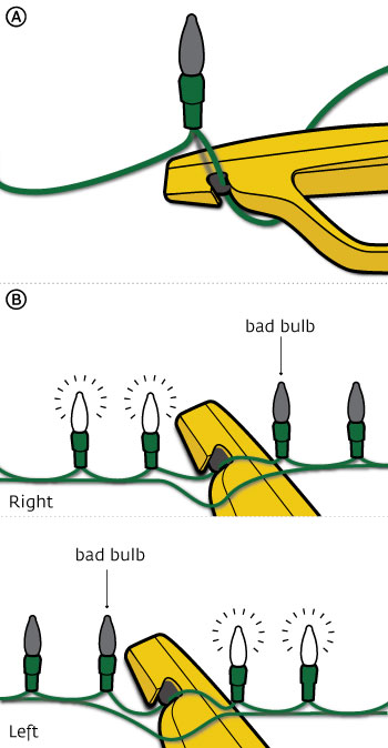
Step 1C: Start about halfway between the place markers. At that point, select a wire that attaches to a bulb socket and place it into the black hook at the front of the LED Keeper (Fig A). Harm will not be caused by piercing the wrong wire.
Step 1D: Pull and hold the trigger. The LEDs on one side of the piercing should illuminate. If not, re-hook and try again. If still no illumination, choose another location between the place markers, re-hook, and pull trigger.
The problem bulb/socket is located in the non-illuminated section. Take the marker from the end of this illuminated section and replace the LED Keeper with that marker on the same side of the bulb as the piercing to mark the spot.
Focus should always be kept on the section that does not illuminate when a piercing is made with the LED Keeper. Continue to narrow down the sections by coming to the halfway points of each and repeating Steps 1C-1D until an individual bulb/socket is identified. This is the point of failure. The LED Keeper should be able to illuminate bulbs on each side of this individual bulb/socket (Fig B).
Note: If still unsuccessful, your light set may have multiple faults caused by rust or other issues. For more assistance, call 888-858-2548.
Step 2 – Repairing the Problem
If the set contains non-replaceable bulbs, go to Step 3.
Remove the suspect bulb, place and hold firmly in the LED Tester on the top of the LED Keeper (No need to pull trigger). The LED Bulb Tester is not capable of testing all bulb sizes. If it does not illuminate in this direction, rotate 180 degrees and re-insert into the LED Tester (See Note Below). If the bulb still does not illuminate, replace it. If the precise replacement bulb required for the set is not available, use a provided Replacement POD (Step 3). Plug the light set into the AC outlet and the set should illuminate. If the set did not illuminate, yet the bulb illuminates in the LED Tester, then the failure may be within the socket. Corrosion or improperly aligned metal contacts within the socket are possible issues. If the socket issue cannot be resolved, continue to Step 3.
Note: A Light Emitting Diode (LED) will only conduct electricity in one direction and illuminate if powered properly. Therefore, it may require two attempts to test the LED in the LED Tester.
Step 3 – Replacement PODs
CAUTION: UNPLUG LIGHT SET BEFORE PROCEEDING
Replacement PODs do not illuminate. They help to maintain the electrical balance after removing a failed bulb/socket from your LED light set. ONCE TIGHTENED, A POD SHOULD NOT BE REOPENED.
Step 3A: Using wire cutters or scissors, cut both wires entering the failed socket as close to the socket as possible.
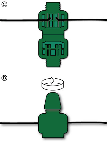
Step 3B: Unscrew the Replacement POD cap counter-clockwise to open the base. Place each of the two cut wires into the “V” shaped channel on each side of the POD’s base. See Figure C. The insulation of the wire does not need to be removed.
Step 3C: After the wires are in place, squeeze the two halves of the POD base together to secure the connection. Twist the cap clockwise until fully tightened (Fig D).
Step 3D: Plug the light set into an AC outlet and the set should illuminate.
Note: For bulbs with 3 wires follow these instructions.